ETC
ETC Television Center User Manual
This manual was written by Dave Linnenbank.
First Edition, April 2017
Chapter Zero: Quick-start Guide
Let there be visuals!
Welcome to The ETC Television Center (or simply ETC to her friends)! Time is money so let’s get you up and running…
Package Manifest
Along with this card, there are two main items in the box you just opened.
- Your ETC. Also note that a tiny white USB drive is also plugged in on the right side of the unit. This drive holds the modes that ETC will use to paint its pictures.
- Its power adapter. While the power supply has prongs for US-style wall sockets, it will work with input voltages from 100 to 240VAC at 50/60Hz. You may need an adapter for the shape of your wall socket.
Getting Started
Follow these steps to make your sound visual.
- Connect the
HDMI Outport to a powered-up HDMI® monitor. - Connect the power adapter to a power outlet, and then connect its plug to the
9VDCpower port, the leftmost port on the back of ETC. The top row’s Status LED will indicate progress, glowing light blue as ETC is booting up, and then white when things are operational. Your connected monitor will also show the boot up process. - Press the top row’s On Screen Display button (its icon suggests a screen with writing on the bottom). Your monitor should now show an overlay of current system information. You can press the button once more to toggle off this display.
- To transmute audio to video, connect a 1/4" audio cable to the
Audio Inport, and turn up the top row’s Audio Input Gain knob. (Feel free to crank it; you won’t hurt ETC’s ears.) As long as an audio signal is coming in, you should start getting pictures on your HDMI display. - When you have had enough fun for now, press the Shutdown button on the top left of ETC. After holding it down for a couple seconds, the Status LED will glow pink while the device shuts itself down. Once the Status LED is off, it is safe to unplug the power supply.
Chapter One: ETC Concepts
What is this box with the curious icons?!‽
Again, welcome to the world of ETC! As this video instrument has an inherent range and can work for different people in different ways, let us start by talking about what it is and where on Earth (or beyond!) it came from. We’ll then look at some of the basic concepts in play and make sure we are speaking the same language. Then we’ll close with a word on using this guide, preparing you to go forth and visually multiply. So back to our origin story…
Where did The ETC Television Center come from?
We at Critter & Guitari (hello!) have released video boxes before, and we are still rather fond of those devices. Their intended use was simple:
- Plug in an audio input, feeding live sound to the box.
- Plug in a live video output for a projector or other display.
- Set a couple knobs.
- Go back to playing music, and live visuals will accompany you.
While ETC preserves this “self-service” approach, a number of other modes and options are present.
Is ETC ready to go out of the box?
Yes! Once ETC is connected and powered up (see chapter zero), it will automatically begin creating visuals with the factory modes.
Does ETC have different methods of creating video?
Yes! You can cycle forwards and backwards through ETC’s current visual modes by pressing the two Mode Selector buttons on the bottom left of the front panel (around the eyeball icon). Each valid patch on the USB stick is loaded as a mode, and the preloaded factory content provides a survey of unique visual effects.
Can I play ETC as a video instrument?
Yes! The knobs and buttons on ETC’s front panel provide direct access to the inner workings of ETC and each available visual mode. To expand your control options, you can connect a pedal to ETC’s Foot Switch port, or even wire up a MIDI controller to the MIDI In port, etc.
Can I just plug in ETC and go back to playing bass?
Yes! If audio is running into ETC, a couple of knob tweaks should get you a steady stream of responsive visuals.
Can I control the ETC with MIDI?
Yes! Do you use a digital audio workstation (DAW) or performance software, like Ableton Live? Gib mir fünf! You can send MIDI to ETC from your DAW, both to directly control ETC’s parameters in an automated way and to create synchronized changes that match your music. In other words, you can now use ETC to take the music you are playing and create a generated, beat-driven video accompaniment. Your audience will thank you (and I hope you are getting a cut of the bar).
Can I capture still images generating by ETC?
Yes! The bottom row of ETC has a dedicated Screenshot button (with a camera icon). Pressing this button will capture the current output of ETC to an image file on the USB drive. And if you are a hacker-type, you could even craft a mode that injects the most recently captured screenshot back into the current output. Think feedback, recursion, or something less imaginable.
Can I feed still images into ETC as source material?
Yes! Modes can be made to use still images from within the mode’s file structure. You might even find some examples of this in our ETC modes repository.
Hold up. Can I edit ETC’s modes?
Yes! All of ETC’s modes are written in Python using the graphics library of Pygame. This means that for the brave, every mode on your USB drive could be edited. And for the truly bold, new modes of your own can be created.
So, there is no “right” way to use ETC?
Exactly! ETC is a vehicle for creating visuals. You may want that in a live performance environment, or you might wish to capture and edit the output. Perhaps you want someone to operate ETC throughout your set, or maybe you yourself just lean over and switch scene presets ever song or two. You might want to get out a text editor and code a custom mode, but you can just as easily download new modes that others have written. Any of these choices are valid as long as they serve your purposes!
ETC Concepts
Our introduction and the sticker on the back of ETC have already hinted at certain ideas and the terms we are using to express them. Let’s take a moment to be clear about the concepts in play.
An ETC mode is a method for creating visuals. In audio terms, you could think of each mode as a patch. The mode can be switched instantaneously from the front panel. Each available mode lives on the attached USB drive along with any support files it may need.
In building the initial factory modes, we have considered modes as falling into two broad categories:
- A scope mode directly visualizes the incoming audio signal. This could take the form of a classic “oscilloscope” signal representation or something far different. Either way, animation is continuously updated with the received audio.
- A trigger mode also visualizes the incoming audio signal, but it doesn’t draw continually as an oscilloscope mode would. Instead, if the audio input’s volume crosses a certain threshold (for example, imagine a snare drum popping), it will trigger a visual. Other events, such as MIDI notes or clocking messages, may trigger visualizations as well. And you can always press the Trigger button to generate a trigger too.
To make things easy to read, a factory mode whose name start with S - is scope mode, and one beginning with T - is a trigger mode. But as the descriptions above suggest, there is plenty of wiggle room as modes can readily blend these ideas or go off in completely new directions. Thinking in the scope/trigger paradigm to start is a good way to both help you understand the factory modes and organize your own ideas for new modes or new even categories.
As for the controls of ETC, we think of them as falling into a couple of categories.
- Foreground controls change parameters of the local mode. Consisting of the four numbered knobs on the front panel, these controls affect settings defined within the currently loaded mode.
- Background controls set global parameters. These include the Background Color knob and the Auto Clear Toggle. Even when you change modes, these parameters are persistent.
An ETC scene is essentially a preset. Each scene stores which mode was being used along with the values of all five knobs (including the four foreground controls and the Background Color knob) and whether the Auto Clear Toggle button is enabled or disabled.
The next chapter will explore how to put all of these ideas into action, but understanding modes versus scenes (and foreground controls versus background controls) will let us hit the ground running.
How to Use This Manual
Certain chapters (such as this one!) are relevant to everyone. But depending on how you plan to use ETC, some information may prove more valuable to you.
- Regardless of your intentions, the quick-start (chapter zero) and concepts information (chapter one) will benefit you.
- For out-of-the-box usage, the information on operating the hardware (chapter two) will be a central guide, walking you through the functions of the various panel controls and ports. And the factory modes reference will walk you through the standard modes and their parameters.
- If you are looking to load additional modes into ETC, then chapter three will also be useful to you. Then you can scour our ETC modes repository.
- If you want to edit modes or even create some of your own, chapter four will help you prepare your work for ETC.
Just realize that how you use ETC today may be very different from how you use it a week from now. This is to say feel free to skip information that isn’t of use to you today; you may find that later chapters appreciate in value over time.
Chapter Two: General Operation of ETC
Knowing the knobs and buttons is worth more than a thousand words.
Up to this point, we have talked about getting ETC plugged in and running, we have discussed some ways to use the device, and we have covered the concepts that underpin the system. So now we should get on with it and make some pretty pictures.
In this chapter, we will walk through ETC from the user’s perspective, with hands fixed on the hardware controllers and eyes on the back panel’s ports. This will naturally address the role and relation of each control within ETC’s structure. Taken as a whole, we will be painting our own picture of ETC’s functions and general operation.
So let’s grab the knobs, push the buttons, and watch the pictures, now, as they fly through the air…
Row 1: Systemic Controls
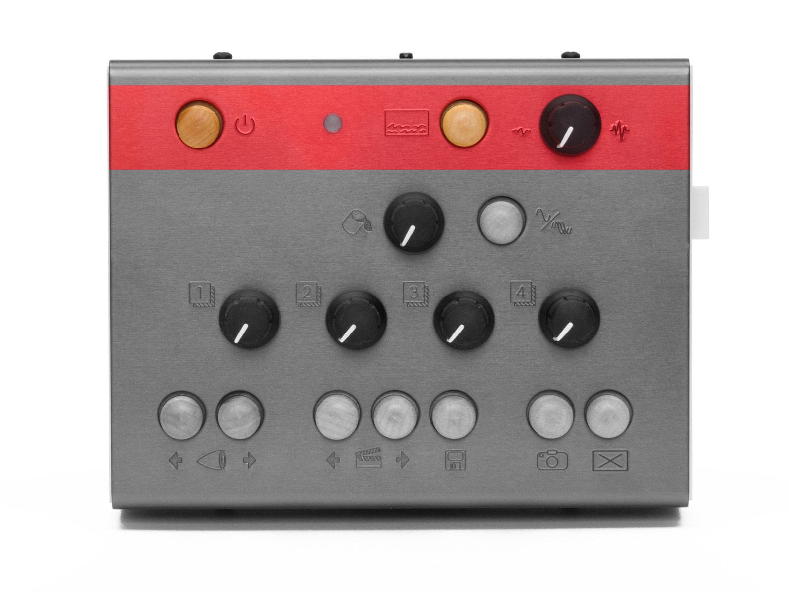
The top row of ETC has a number of system-level controls and the only direct feedback element that faces the user. We will take these items from left to right.
The Shutdown button is a trigger that does exactly what its name implies: it tells ETC to begin shutting the system down.
When ETC is connected to power, the system automatically begins booting up (as described in chapter zero). When you are done using ETC or need to power it down for a moment, hold down the Shutdown button for two seconds or so. During the shutdown process, the Status LED will go from white to pink, and once the unit is ready to be safely unplugged from power, the light will finally go out .
The Status LED is a light that illuminates in various colors to reflect either the state of the ETC hardware, or to indicate that a particular action is being taken or a type of message was just received.
When the Status LED is glowing in one of these colors, it is indicating the following hardware state:
- Light blue: ETC is currently starting up. (It has probably just received power.)
- Red: ETC encountered an error while starting up. If you consistently receive this message, either consult our FAQ page or contact us!
- White: ETC is currently running normally.
- Pink: ETC is in the process of shutting down. (You likely just pressed the Shutdown button.)
- Dim: When the LED is not illuminated, then ETC is not running. Either you haven’t powered it on yet, or you have already shut down the device.
And when the Status LED is showing one of these colors, it is relaying the following information:
- Yellow: A screenshot is being written to the USB drive. (You likely just pressed the Screenshot button.)
- Green: When the LED flashes green, a MIDI message (such as a note or continuous controller message) was just received by ETC. When the light stays a solid green, a steady stream of MIDI messages (likely clock messages) is arriving at ETC.
- Purple: A message was just received via the
Foot Switchport.
The On Screen Display button is a toggle that calls up an overlay of current system information.
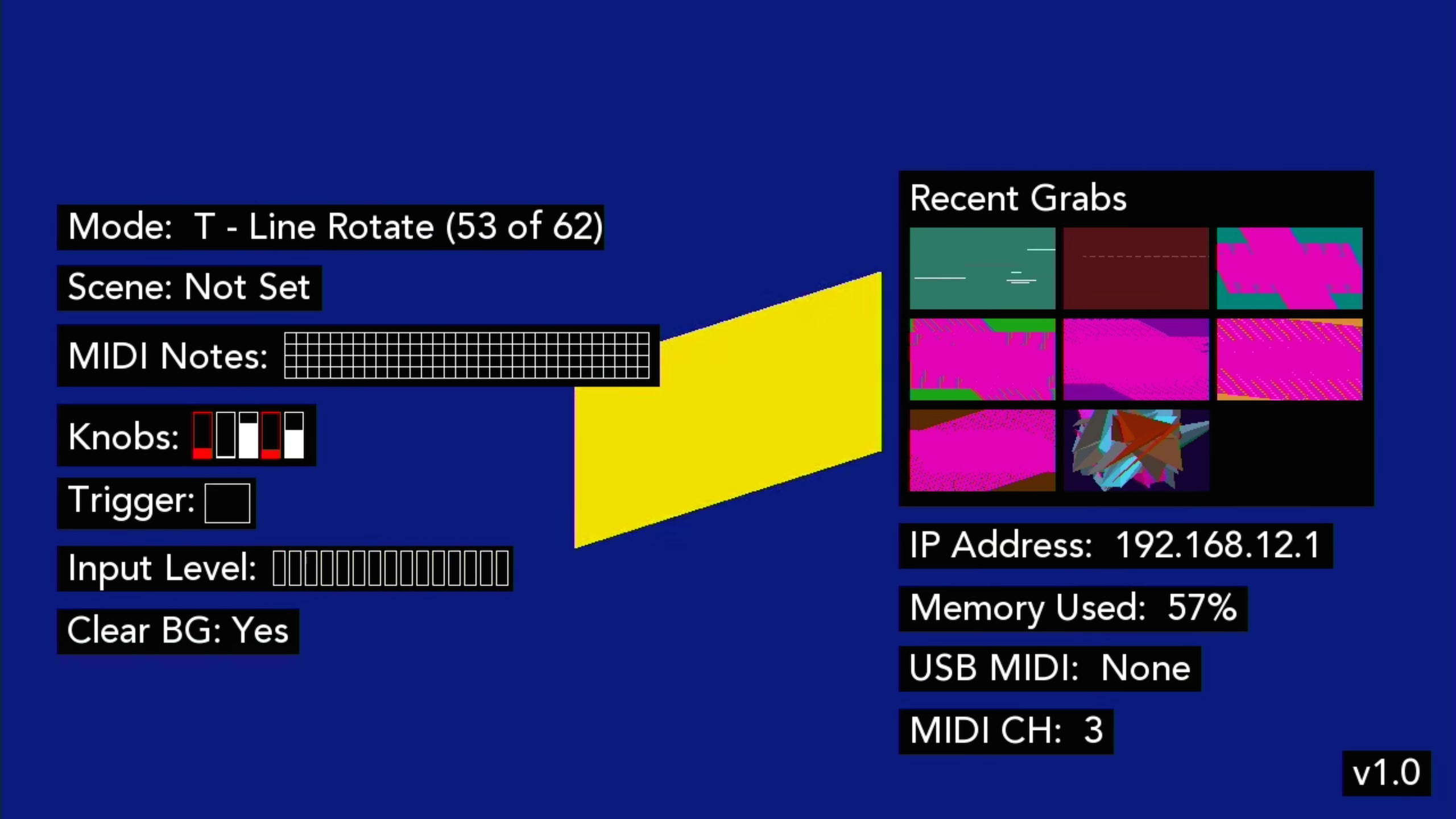
Information is displayed in two columns. On the left side are:
- The current mode.
- The most recently loaded scene (if applicable).
- An indicator for incoming MIDI notes.
- The current positions of the background and foreground knobs.
- An indicator of whether the threshold trigger is currently engaged.
- A level meter for incoming audio signal.
- An indicator of whether the background clearing function is currently enabled.
The right column includes:
- Thumbnails of the several most recent screen grabs.
- ETC’s current IP address, in case the USB Wi-Fi dongle is in use. (For more information, see chapter four.)
- How much of ETC’s memory (RAM) is currently being used.
- Any connected and recognized USB MIDI devices (if applicable).
- The incoming MIDI channel that ETC is listening to.
Pressing the On Screen Display button a second time will toggle the display back off screen.
The Audio Input Gain knob does nothing to affect the internal video system or change the audio that you hear, but it is probably the most consequential control for ETC. This knob scales the incoming audio level before it is processed by ETC for use in the current visual mode. The purpose of this knob is to adjust the strength of the audio signal and scale it into an appropriate range for visualization.
The appropriate setting for this knob will depend on the type of signal you are connecting and the mode you are using. For example:
- Are you connecting a guitar or microphone directly to ETC’s
Audio Inport? Then you will probably need a higher gain setting for this relatively weak signal. - Are you connecting a powered instrument (such as a synthesizer) output, or even the full band’s output from a mixer? Then the Audio Input Gain knob can probably be a bit lower.
- Are you doing something we can’t imagine? Good job! Adjust the gain knob until you find an appropriate setting for the modes you are using.
Row 2: Background Controls
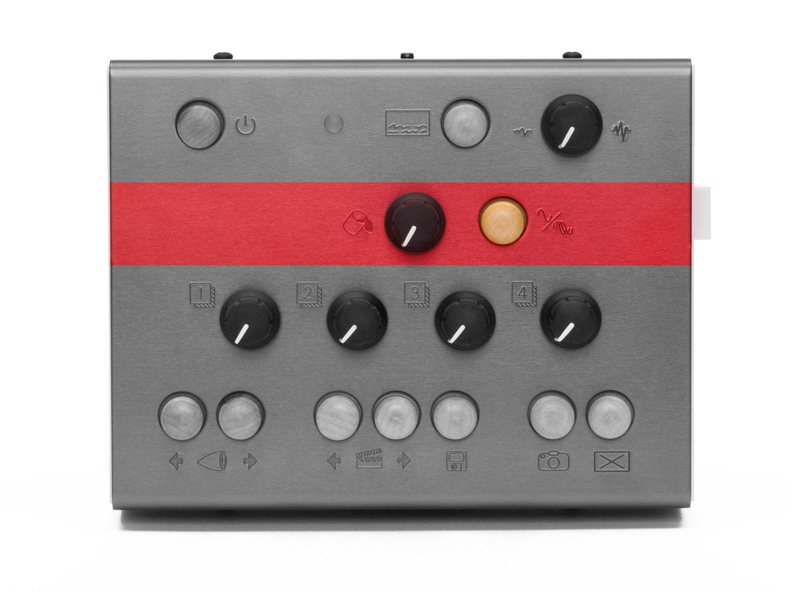
While the second row is the most sparsely populated, its two controls are really the glue that hold transitions together for ETC. These background controls set global parameters that are held steady not matter what mode you are in or if you recall a scene.
The Background Color knob allows you to set the “canvas color” on top of which mode paints its scene. Turning this knob cycles through the available colors.
The Auto Clear Toggle button is a nice toggle effect available in all situations. This is easier explained with a brief word on how ETC carries out its drawing functions.
Each ETC mode contains one draw function, which is triggered 30 times per second to generate 30 frames per second (FPS) of output. The default behavior for a drawing program like this is to clear the screen right before the draw function is run. (This clearing results in the color set by the Background Color knob covering the screen.) But breaking the rules can be interesting.
The Auto Clear Toggle button allows us to disable this clearing function. When clearing has been toggled off, each new frame of video draws on top of the previous frame, which can create a “hall of mirrors,” recursive effect. Hitting the Auto Clear Toggle button again restores the normal clear function.
So there is a dependent relationship between the Auto Clear Toggle button and the Background Color knob. When clearing has been toggled off, the Background Color knob has no effect since the background is never getting painted. When the button is toggled back to normal clearing behavior, the set background color will be applied again.
Row 3: Foreground Controls
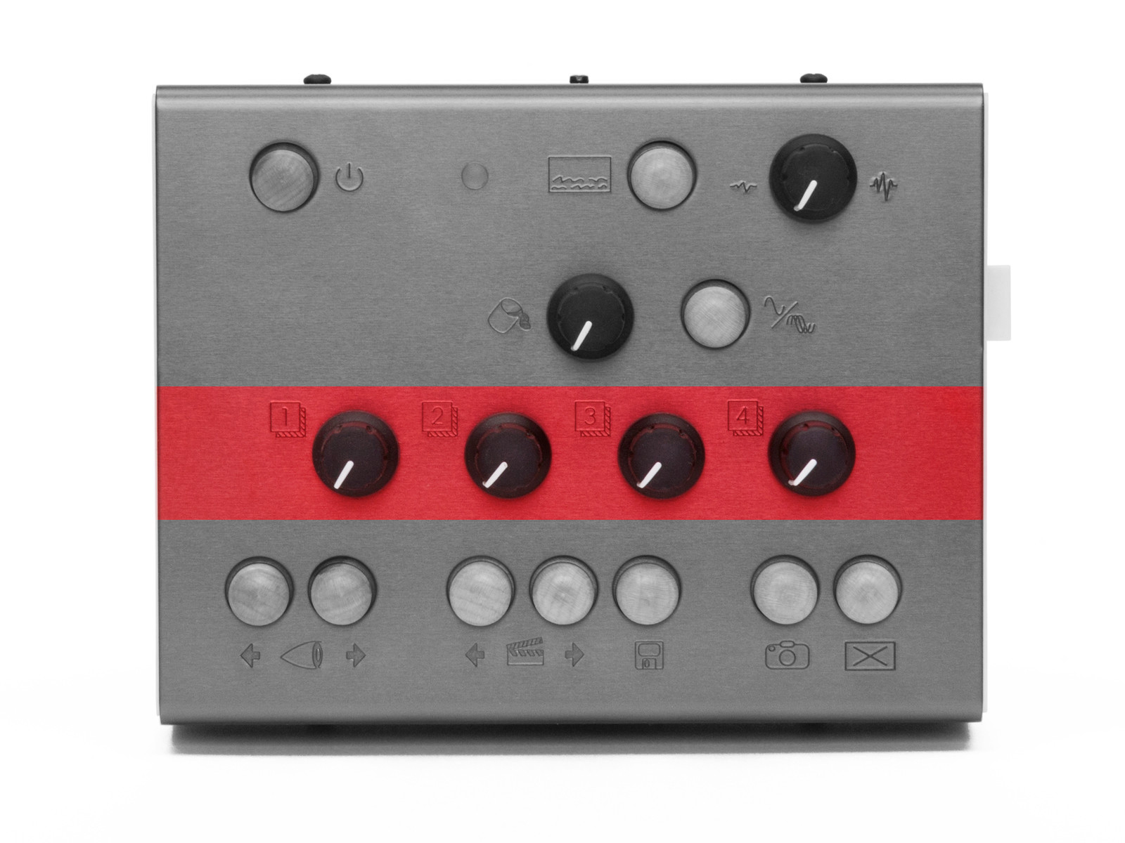
The third row consists of four numbered knobs. Formally, we could call them Foreground 1 Control knob,Foreground 2 Control knob, etc. Or we could be more collegial and simply call them foreground knob 3 and foreground knob 4. Either would be appropriate.
Each of these foreground controls represents a top-level parameter within the mode. This could be a single parameter that controls one discrete element of the mode, or it could be several parameters wrapped into a true “macro” function. While we don’t know the specifics for each mode (see the factory modes reference for that type of per-mode information), we know that each patch should have four top-level controls, and that these knobs pull the strings to make each mode its own instrument.
We spoke in chapter one about the difference between modes and scenes, but an additional word is appropriate here on how the foreground knobs behave when moving between modes and scenes.
When you load a different mode, the current values of the foreground knobs are maintained for the new mode that is loaded. In other words, if you just turned foreground knob 1 to 3 o’clock and foreground knob 3 is set to 10 o’clock, ETC will supply those exact same settings to any successive modes that you load.
If the foreground knobs are assigned consistently across different modes you are using, this can offer more stable transitions between modes. For example, if you have loaded several modes that use foreground knob 4 as a uniform color selection parameter, then that setting would be interpreted similarly as you switch from mode to mode, using that same color value across successive modes. And even if your modes assign their foreground knobs in completely different ways, ETC’s behavior will at least preserve your settings when you switch over to another mode and then back to your original selection.
When you load a different scene, the current values of the foreground knobs are ignored in favor of the settings stored in the scene. In other words, loading a scene will load the scene’s stored foreground control values into ETC, leaving no connection (for the moment) between the values currently used by the software engine and the physical position of the foreground control knobs.
As we discussed in the concepts portion of chapter one, each scene is basically a snapshot of ETC’s current mode state. This includes the mode that is being used as well as the value of each of the foreground controls at the time the scene was captured (and the values of the Background Color knob and the Auto Clear Toggle button). While turning the foreground knobs and switching between modes offers an “organic” experience, loading a scene is a relatively abrupt act, jumping directly to settings that were stored at another time, in another place. This is by design.
Turning a foreground knob is always an absolute gesture: as soon as a change in the knob’s value is detected, it will be applied to ETC’s video engine. This holds true after a scene has been loaded. By turning a foreground knob, the new value there will take over, replacing the scene’s stored value and restoring the connection between the physical control and the software. Again, this may be an abrupt gesture at first — particularly if the stored value and the current knob position are on opposite sides of the control range. But once the knob is turned, all successive tweaks will create smooth value transitions.
And as for how to switch between different modes and scenes (and store new scenes), well it’s funny that you ask…
Row 4: Functional Controls
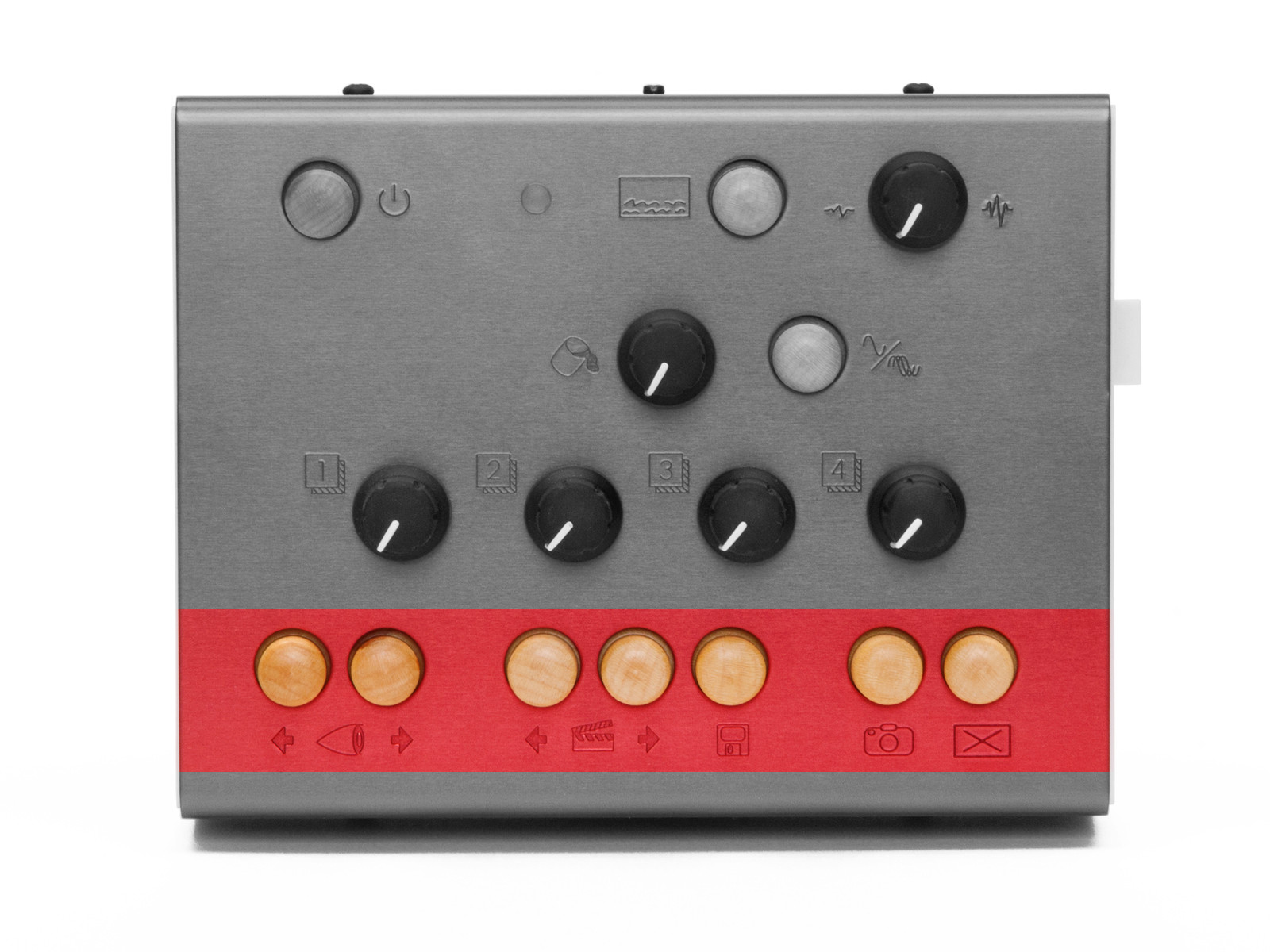
The top bottom of ETC has a number of navigation and action-based options, all in the form of tasteful maple buttons. We will look at each niblet, going from left to right.
The Mode Selector buttons are first up. This pair of trigger buttons on the far left around the eyeball icon allow you to step backward (left) or forward (right) through the modes that are currently loaded on your USB drive.
The Scene Selector buttons are next. This pair of trigger buttons around the clapperboard icon allow you to step backward (left) or forward (right) through all stored scenes.
The Scene Save button follows the Scene Selector buttons. This trigger button with the floppy disk icon (remember those?) takes various performance values — your current mode selection, the values of all four foreground controls, the background color setting, and the state of the Auto Clear Toggle button — and stores them to a new scene. This new scene is placed at the end of the scene list.
Additionally, pressing and holding the Scene Save button for about two seconds will delete the most recently loaded scene. So if you called up a scene and wanted to re-save it with some adjustments, first hold the Scene Save button down for a couple seconds to delete the original scene. Once you have found settings you are happy with, then press and release the Scene Save button as usual to write the new scene into memory. (Just release that the new scene will be placed at the end of the current scene list.)
The Screenshot button is a trigger with a camera icon. When pressed, the output of the current video mode is captured to a still image file on ETC’s USB drive. Screenshots created will not include the On Screen Display, even if this overlay is currently visible via the HDMI Out port.
Output files are number from zero (0), are saved as JPEG files (for example, 0.jpg, 1.jpg, and so forth), and share the specs of ETC’s video output: 1280 pixels wide, 720 pixels high, and a resolution of 72 pixels per inch (PPI).
To access these files, first safely shutdown ETC. You can then connect its USB drive to your own computer. All screenshots will be located in the Grabs folder in the drive’s root (or top) directory.
The Trigger button is on the bottom right of the panel, and its icon is a rectangle containing an X, marked for action! Pressing this button triggers an assigned visual function within most modes. This trigger action is the equivalent of having audio from the Audio In port cross the threshold. It is most commonly used in trigger modes (as discussed in chapter one), but any mode can connect a function to the threshold behavior.
Pressing the Trigger button will also fill ETC’s buffer of recently received samples with a sine wave. Together with the threshold trigger behavior described above, these two functions make the Trigger button a useful substitute when you do not have audio flowing into ETC. With that being said, many modes can also make use of these trigger messages to supplement incoming audio signals so do try it with all kinds of modes.
The Ports
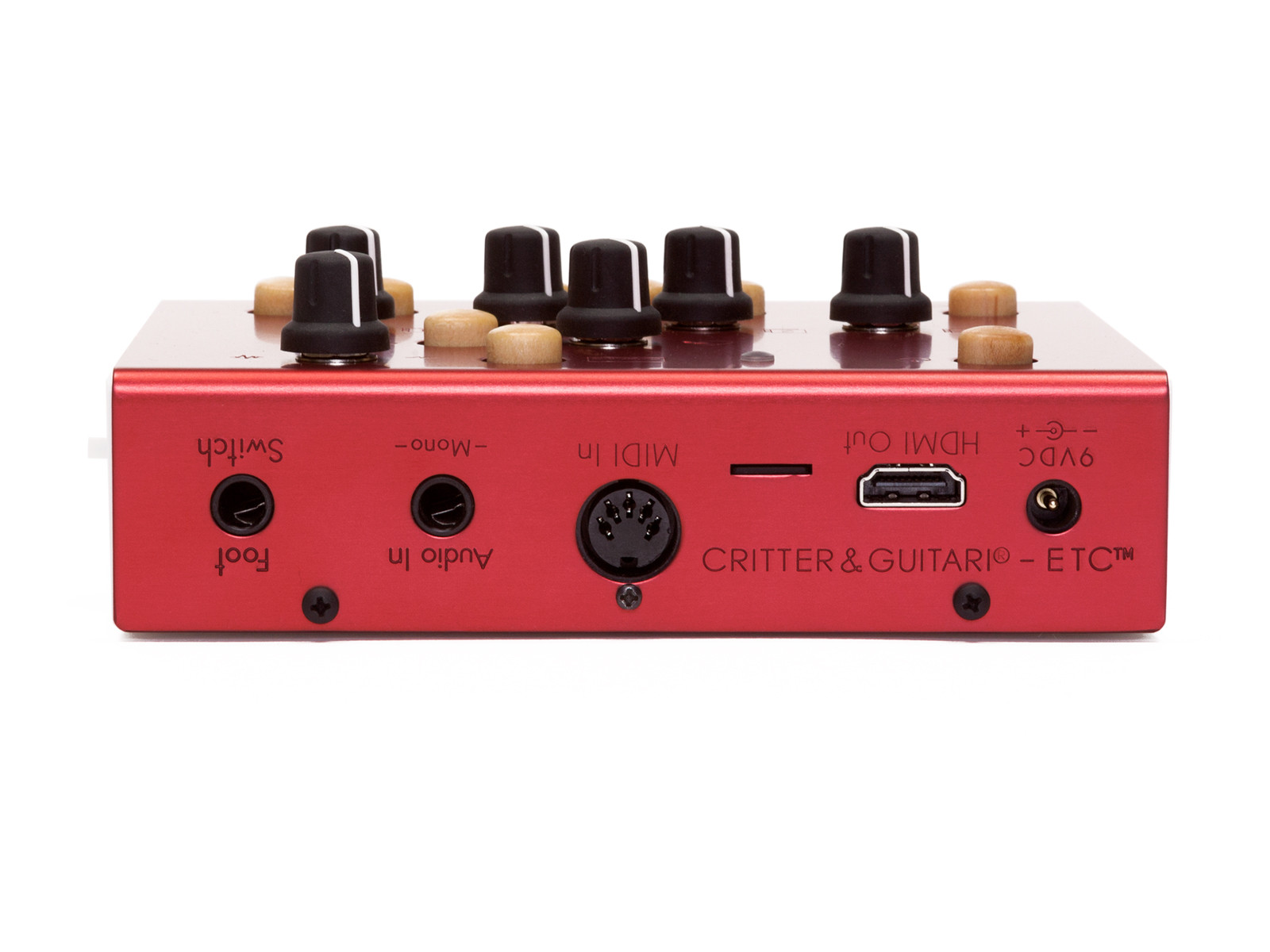
Most of the ports are on the back of ETC, and many of them have already come up in our conversation, but we’ll take a moment to touch on each of them with any information relevant to this conversation of general functionality.
The 9VDC power port is made for the power supply including with ETC. As with all Critter & Guitari instruments, the power supply’s output specifications are as follows: 9VDC, 1000mA, and a tip with center-positive polarity. If you are uncertain whether a power supply will work with ETC, don’t plug it in to find out.
The HDMI Out port serves as the video output for ETC.
Next is an unlabeled microSD card slot. This slot comes preloaded with a card that serves as the internal microcomputer’s root disk. We do not recommend ejecting or otherwise manipulating this card as nothing good will come of it.
The MIDI In port is for connecting an external MIDI controller. Information on ETC’s MIDI implementation is found in chapter three.
The Audio In port is a -Mono-(phonic) 1/4" input for audio signal. This audio is made available to your modes in two ways. First, a list of the most recent 100 samples is always available for drawing purposes. And second, the incoming audio is continually assessed to determine if it exceeds a threshold level (roughly 80% of maximum possible amplitude), highly useful for commencing a function.
The Foot Switch port is a 1/4" jack. It is intended to be connected to a keyboard sustain-/damper-style pedal.
If scenes are stored on your USB drive, an “on” message received at the Foot Switch port advances to the next stored scene. If no scenes are present on the USB drive, each message loads the next available mode instead. In both cases, this action “wraps around,” going from the last available scene/mode back to the first one, and so on.
ETC assumes that any connected foot switch has a “normally open position” (positive polarity).
Finally, the two USB ports reside on the right side panel. We already mentioned the tiny USB drive that comes with ETC and must be connected for the device to properly boot up. For more information on working with the USB drive and its formatting, see chapter three.
If you need more USB ports, you could connect a hub to one of these ports. That hub and any other devices you connect should be class compliant, meaning that is doesn’t require a special software driver to be installed. This will help to ensure compatibility with ETC.
An Epilogue on Basic Controls
Note that we aren’t discussing how to produce certain types of images or effects. While the controls offered by ETC are always the same, each mode is unique its own right and can be used in ways that even we can’t imagine. Do consult the factory modes reference for a sense of the included options and their range. And if those provided options aren’t enough, then continue with us to the next chapter.
Chapter Three: Accessing ETC from Elsewhere
Getting into and out of ETC.
First, we are glad you made it this far! And just in case you skipped straight to this chapter, be sure to go back and read chapter two! We are assuming that general operation of ETC is fairly clear at this point. So with that out of the way, let’s proceed.
In this chapter, we are going outside of ETC itself to focus on how it interacts with the wider world. While ETC can be run successfully with its factory modes and its own on-board controls, you can definitely expand this performance device with new modes and/or additional sources of control. Here we will see ways to grow ETC’s range in each of these dimensions.
We will start with some basics, looking at the folder structure used by ETC’s USB drive, where your modes and screenshots all live. If you want to load additional modes or simply download your screenshots, you will need to work with the USB drive (and your own computer) to place the new modes and their support files in the right place. Second, we will look at accessing the USB drive by connecting it to your computer. And finally, we’ll look at ETC’s MIDI implementation. This will be useful if you want to connect external MIDI — including USB MIDI — controllers to ETC, or even if you pair ETC with an external sequencer.
If you are searching for additional modes of expression, you have come to the right place. Let’s make ETC that bigger boat…
The USB Drive’s Folder Structure
As has been mentioned, ETC will only properly work while a USB drive is attached to it. Modes are run directly from this attached USB drive. (While not mission-critical, scenes and screenshots are also stored to this drive.) This could be the flash drive included with ETC or another USB disk that is appropriately set up. Some rules apply:
- This USB disk should be formatted with a FAT file system, often associated with MS-DOS.
- This USB drive must contain a folder called
Modesat its top-level. (This name is case-sensitive.) All modes to be loaded must live here, as detailed below. - The top-level of the USB drive may also contain a folder called
Grabsfor housing screenshots that are taken, a file calledScenes.csvfor recording all scenes that are stored, and aMIDI-Channel.txtfile that sets the incoming MIDI channel that ETC listens to. If absent, these items may be automatically created when needed.
The following is an example directory listing of an ETC-ready USB drive. You can see four modes here, each with a required main.py file, as well as the Grabs folder and a Scenes.csv file.
Grabs\
	0.jpg
	1.jpg
	2.jpg
MIDI-Channel.txt
Modes\
	S - Circle Scope Connected\
		main.py
	S - Feynman\
		main.py
		main.pyc
	T - Density Cloud\
		main.py
		main.pyc
	T - Spanish Flash Cards\
		font.ttf
		main.py
		main.pyc
		spanish.py
		spanish.pyc
Scenes.csv
A couple items worth noting here about the modes:
- In the four mode folders shown above, all of them have the required
main.pyfile. As long as these Python script files contain the minimum requirements for an ETC mode, they will all be treated as valid modes and loaded when the device starts up. (For information on programming or editing modes, see chapter four.) - Three of these mode folders also include
main.pycfiles. These intermediary files are automatically created by the Python compiler in ETC. These files can speed up future interpretations of their script, but the PYC files are not required or needed. (The first mode listed here has nomain.pycfile, suggesting that it is a new mode which has not yet been run by ETC.) - Other files necessary for your mode should also be included in the mode folder. This could include images, additional Python scripts, font files, or anything else that might make sense.
- Also note that mode folders can also contain subfolders, which can be recognized by contained mode.
Taking the USB Drive to your Computer
Whether you want to load new modes, download some of your screenshots, or edit the Scenes.csv file or the modes themselves, any of these actions requires accessing the files on ETC’s USB drive. One way to do that is connecting the USB drive to a computer. We will discuss that here. (A second way to edit modes is with the USB Wi-Fi interface [a separate purchase] for wireless access. We will cover that in the chapter four.)
If the USB drive is currently connected to ETC, you must first shut down the unit by holding the Shutdown button for a couple seconds. You will then see the Status LED turn pink while the system is shutting down, and then the LED will go dim. Only when the Status LED has gone out is it safe to disconnect the USB drive.
When using the included USB drive, be sure it is flipped the right way before connecting to your computer. The drive that comes with ETC has an extremely low profile, consisting of the bottom half of most standard USB connectors/cables. As such, it is possible to plug the drive in upside down. This is generally harmless but is better avoided.
Be sure that the exposed pins — I think of them as teeth — are facing “up,” toward wherever the top of a connected USB cable would go. (On Mac laptops, for example, the pins should face upward, toward the sky.)
Once the drive is connected and seen by your computer, it would appear somewhat like the following.
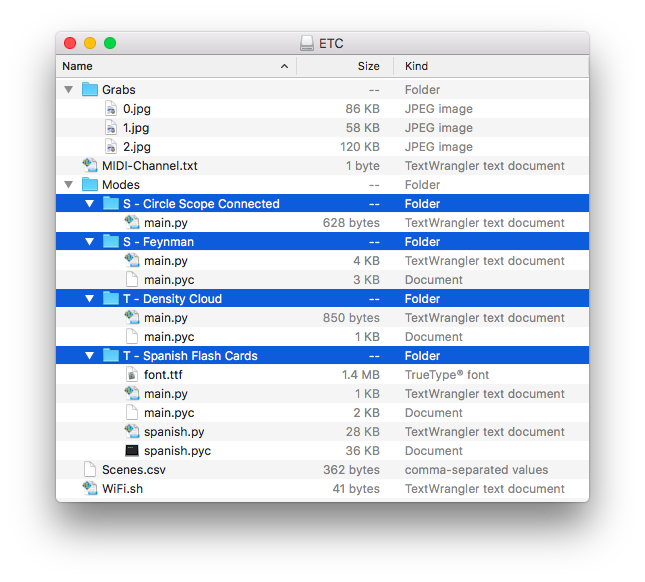
The top level of my USB drive, whose disk name is ETC, is shown above. This root-level does indeed contain the Grabs folder, where three screenshots have been stored. Now would be a good time to move those images to your computer for your own use.
A suggestion about screenshots. While you could copy files to your computer and leave them in place on the USB drive, a better practice is to regularly remove your screenshots from the USB drive. It is easy to run out of space on the USB drive by amassing screenshots, either slowly or quickly. Instead of running low on space without realizing it, just remove these images regularly.
Also at the top level is the Scenes.csv file. This file of comma-separated values is readable if you open it in a text editor, with each line looking something like this:
bouncing-ball,0.0,0.2668621700879765,0.5141739980449658,0.7526881720430108,1.0,False
These values represent:
Mode, Foreground 1 Control knob, Foreground 2 Control knob, Foreground 3 Control knob, Foreground 4 Control knob, Background Color knob, Auto Clear Toggle button
If you are brave and interested, you could try editing these scenes values or simply reordering the lines. But you might want to make a local copy of the file first, just in case. (If things get out of hand, you can always just deleted the Scenes.csv. When a new file is needed, ETC will create it.)
Inside of the top-level Modes folder, the four modes are selected (with blue coloration), and their contents are exposed. So in the example shown above, the four modes available on ETC would be S - Circle Scope Connected, S - Feynman, T - Density Cloud, and T - Spanish Flash Cards. And once more, the practice with factory modes is that a leading S - indicates a scope mode while a leading T - signifies a trigger mode (see chapter one).
When working with these modes, you will most likely want to work with their folders rather than handling the files within each folder. For example:
- If you want to add a new mode to ETC, make sure to copy the full folder into the USB drive’s
Modesfolder. (And if you downloaded a ZIP file, make sure that you have decompressed it to a folder before moving it to ETC’s USB drive.) - If you want to back a mode up, copy the folder over to your computer.
- If you want to rename a mode, rename the folder.
- If you want to duplicate a mode and make changes to the new copy, duplicate the folder and name the copy something different.
- If you want to delete a mode, make sure to delete the entire mode folder.
In short, if you aren’t editing the files themselves, then working with the files within the mode’s folder can only cause problems.
Finally, note that any other folders or files located on the USB drive will likely be ignored by ETC. This means you could keep a backup folder of working modes on the USB drive while editing the “live” versions. Or this could be handy for having different “set lists” of modes or even different scene files. The set list idea would be to duplicate either your Modes folder or Scenes.csv file, and then rename the version that you would like to save for future use. Just make sure that the proper files and folders have the proper names before you hit the stage!
ETC’s MIDI Configuration
As ETC’s MIDI In port suggests, external MIDI controllers can be connected to it. In addition to devices connect by regular(/old-fashioned) five-pin DIN connectors, USB MIDI devices can also be used with ETC. To ensure compatibility, we suggest that you select a class compliant USB MIDI controller. Any controller that requires the installation of a driver may, at best, not work as expected.
To properly interact with ETC, we need to know the MIDI implementation of this device. To begin with, ETC only listens to incoming MIDI messages that are on the specified channel (by default, MIDI channel 1). And only a small subset of MIDI messages has an actual effect on ETC’s operating modes.
In other words, your controller may send some messages that ETC doesn’t recognize, and that’s okay. These messages won’t produce any effect on ETC, but they won’t create any problems either so don’t worry with “disabling active sensing,” etc. etc.
Let’s start by examining the different type of messages that ETC uses. We will also end with a word on changing the incoming MIDI channel that ETC responds to.
Control Change Messages
Incoming control change messages using controller numbers 21 through 25 have an effect on ETC. The following knobs correspond to the listed controller number:
- Controller Number
21> Foreground 1 Control knob - Controller Number
22> Foreground 2 Control knob - Controller Number
23> Foreground 3 Control knob - Controller Number
24> Foreground 4 Control knob - Controller Number
25> Background Color knob
Each incoming message’s value replaces the current value of the respective controller. So even if foreground knob 2 is turned all the way to the right, an incoming controller message of number 22 with a value 0 will change foreground controller 2’s value to zero. Once you move the Foreground 2 Control knob again, its control will be restored.
Program Change Messages
Program change messages received by ETC switch to the scene specified by the message’s value. So if a program change message with a value of 1 is received, ETC will switch to its first stored scene, and a program change message with value 4 would switch to the fourth scene, etc.
If no scenes are stored on ETC, then these program change messages will similarly map to the loaded modes. So a program change message with value 1 would switch to the first mode, 9 to the ninth mode, etc.
Note Messages
All incoming note messages (again, on the global MIDI channel) are received by ETC. It provides information on these note messages in two ways:
- ETC tracks all incoming note messages, keeping tabs on which pitches are on or off at any given time.
- A lot like a flag on a mailbox, ETC provides a notification whenever a MIDI note on message(s) has been received since the previous video frame. This can be very handy for creating a “note trigger” effect in your modes.
Any mode can use either or both of these status data.
Additionally, the last MIDI note (pitch 127) is used to toggle that state of the auto clear function, acting in the same manner as each press of the Auto Clear Toggle button. So any note on message with pitch 127 toggles the current state (if it was on, it switches off, and vice versa).
MIDI Clock Messages
ETC also understands a couple of MIDI system real-time messages. Many sequencers support this clocking method, but it is simple enough that you could build it into other environments as well (such as Pure Data [read: for Organelle], Max, Reaktor, etc.).
MIDI’s concept for system real-time messages is that a timing clock message is received 24 times per quarter note for the purposes of synchronization. Accordingly, each time ETC receives a timing clock message, an internal counter is increased by one step. After the 24th step, the counter returns to its low position and counts upward again. Additionally, any real-time start message that is received triggers also causes the counter to be reset on the next clock beat.
This internal counter value of ETC is accessible to any mode that wishes to use it. By using select steps of the counter, you can create effects that are rhythmically synchronized to your liking.
And please note that MIDI clock messages are system MIDI messages. That means that these messages will be received and used regardless of ETC’s current global MIDI channel.
Changing the Global MIDI Channel
Earlier we noted a file called MIDI-Channel.txtat the top level of the USB drive. This plain text file should contain only a single number. If the number is between 1 and 16, then ETC will listen only to that specified MIDI channel for incoming MIDI messages, and all other channels will be ignored.
Setting the contents of the text file to 0 (the number zero) will switch ETC to a kind of omni mode, telling the device to ignore the MIDI channel of incoming message and to respond to everything it receives. As an example, this might be preferable if you are using a MIDI controller that has both keys and/or knobs (typically transmitted on channel 1) and drum pads (often sent on channel 10).
Finally, if this MIDI-Channel.txt file is deleted or not readable, ETC will default to MIDI channel 1 when it boots up.
Chapter Four: Programming For ETC, and Access via Wi-Fi
For those with a text editor and a dream.
Well, here we are. The place where dreams and/or ETC modes are made.
First of all, this chapter may not be for you. If we may say so ourselves, ETC is rather functional and expressive without getting into coding. So if you are comfortable with using ETC and would rather stick with the artistic side of your brain, that is great. Focus on what is going to benefit you the most, and go in peace. If you ever want to come back, we will be here. Waiting.
And while this chapter focuses on how ETC works and the methods available to you within this framework, we are not going to teach you how to code. We don’t have enough pages or Red Bull to do that here. But don’t despair. Now more than ever, there is a bounty of resources available that will help you learn about programming in general and about particular languages (such as Python). Searching the internet, the library, or even local computer classes on offer will give you some good leads and help you find a way forward to start programming.
Now, if you enjoy coding already (or are considering it), or if you have some video ideas that you need to express, then let’s proceed. Just pull that lever to pop the hood.
In this chapter, we will start with the concepts and requirements for any ETC mode. Each mode doesn’t require much, but talking about what does need to be there will give us a good picture of how ETC operates. We will then outline ETC’s application program interface (API). Beyond the required pieces, these are the available functions and properties that you can make use of in any mode. Finally, we will look at connecting to ETC for the purpose of editing modes directly while the device is running. This can be done via the optional USB Wi-Fi interface, which is an additional purchase.
So this is the road before us. We have already seen how ETC handles; now let’s change the oil and what make him purr…
How Mode Scripts Work
A word or two on how ETC actually does its work will go a long way. We will spend a moment on the languages at play and the system behavior of ETC, and then we will talk about the basic requirements of a mode.
Python, Pygame, and ETC
As was said early on, ETC’s modes are written in Python using the graphics library of Pygame. So Python is the programming language in use, and the graphics library executing the drawing comes from Pygame.
Python has a rich standard library with numerous modules, any of which can be used in your modes. A full list of modules can be found in Python’s documentation. Going through the factory modes, you will see such modules as glob, imp, math, random, and time in use. To learn more about how any of the library modules work or more about Python itself, the documentation link above is a wonderful place to start.
Pygame is a set of Python modules that were originally written for video game development. ETC is using the graphics library of Pygame to create our visuals. A full list of available modules can be found in Pygame’s documentation under the Reference section. Some of the factory modes make use of additional libraries such as pygame.freetype and pygame.gfxdraw, but other graphics-related modules could be used as well.
Pygame renders its graphical output to a surface. This is how we connect our Python scripts to our Pygame output, which we will see in the next section.
When ETC starts up, it identifies all valid modes within the USB drive’s Modes folder. And it then loads all of these modes simultaneously. This parallel behavior is what makes switching between modes so instantaneous and smooth, but it also adds a couple of things worth considering:
- A memory-intensive mode will always be running. If you load a mode that requires a significant amount of RAM (say, for loading numerous images during
setup()), realize that this memory will be taken up even when another mode is called up and generating output.
So if you encounter laggy performance of ETC in general, realize that this could very well be one of your modes hogging memory. One way to troubleshoot this would be to load fewer modes (by moving additional modes out of theModesfolder) during testing. - Keep your support files to a minimum. Again, a good example would be a mode that loads images. We’d advise you to keep the images within a mode folder to 10MB or less. Your mileage will definitely vary, but that is our one-size-fits-all suggestion.
Also note that the size of loaded image files could often be optimized. If you download a photo straight from your camera or phone, you’d do well to reduce the resolution to something closer to or below ETC’s output resolution (1280 by 720). As with all rules, there can be exceptions, but there you go.
Minimum Mode Requirements
Each mode has only four basic requirements for successfully being loaded and to (hopefully) produce graphical output:
- Load the “pygame” module. As with any module in Python, this is done with a leading
importstatement. So any ETC mode script should begin with…import pygame - Have a “setup” function (please). This is actually optional but highly suggested.
setup()will get called automatically when the mode is loaded. This is a clean way to run any operations that are only needed once, before video is being rendered. - Have a “draw” function.
draw()is the function that is run 30 times per second (think 30 frames per second [fps]) to paint each frame of video output. Common activities here including taking in any control changes since the last frame, redrawing with updated audio information, executing changes based on any trigger or other messages received, etc. etc.
Note that code in this block will get hammered so please be a bit parsimonious, only including actions that need to be taken for each and every frame. - Route your output to the “screen” surface. ETC creates a reserved Pygame surface called
screen. This surface is what gets sent out for display via the HDMI port.
A Simple Mode Example
Taking all of these points into consideration, here is a very simple example ETC mode…
import pygame

def setup(screen, etc):
	pass

def draw(screen, etc):
	size = 640
	position = (510, 500)
	color = (255, 0, 0)
	pygame.draw.circle(screen, color, position, size, 0)
Walking through this basic main.py example, we start by loading the pygame module, as outlined above in step one. We then define a setup() function. This one is blank, but it is good to have as a placeholder for use when necessary.
Next comes the draw() function. The first three lines of the function are defining local variables that are used in calling the pygame.draw.circle() function. And as the first argument in the example indicates, this function is pointing at the screen surface, getting our draw messages out of ETC through the HDMI output port.
That is about the simplest mode we could make, and its result is equally simple — a red circle is drawn near the middle of the screen, each and every frame, forever. This example offers the basic framework for examining the factory modes and for understanding how to structure your own modes. Our only suggestion is an obvious one: you should probably send different images out of ETC from time to time.
ETC’s API
Having walked through the general framework and requirements of ETC’s modes, it’s time to take a look at the API available when working with ETC. The etc object contains a number of variables, all of which can be accessed from any mode:
etc.audio_in- A list of the 100 most recent audio levels registered by ETC. These values are stored as 16-bit, signed integers, ranging from a minimum of -32,768 to a maximum of +32,767.
Additionally, depressing the Trigger button populates this list with a sine wave, simulating audio input to ETC.etc.audio_trig- A boolean value indicating whether or not incoming audio has exceeded the fixed threshold level (approximately 80% of maximum) since the last frame was drawn via thedraw()function.
Additionally, depressing the Trigger button setsetc.audio_trigtotrue.etc.bg_color- A tuple of three integers representing the red, green, and blue components of the current background color.etc.knob1- A float representing the current value of the Foreground 1 Control knob.
Additionally, an incoming MIDI control change message of number21on the current global MIDI channel will replace the value of foreground knob 1, until the knob is moved again.etc.knob2- A float representing the current value of the Foreground 2 Control knob.
Additionally, an incoming MIDI control change message of number22on the current global MIDI channel will replace the value of foreground knob 2, until the knob is moved again.etc.knob3- A float representing the current value of the Foreground 3 Control knob.
Additionally, an incoming MIDI control change message of number23on the current global MIDI channel will replace the value of foreground knob 3, until the knob is moved again.etc.knob4- A float representing the current value of the Foreground 4 Control knob.
Additionally, an incoming MIDI control change message of number24on the current global MIDI channel will replace the value of foreground knob 4, until the knob is moved again.etc.lastgrab- A Pygame surface that contains an image of the last taken screenshot taken (via the Screenshot button). This surface has dimensions of 1280 by 720, matching the full size of the screenshot.etc.lastgrab_thumb- A Pygame surface that contains a thumbnail image of the last taken screenshot taken (via the Screenshot button). This surface has dimensions of 128 by 72.etc.midi_notes- A list representing the 128 various MIDI note pitches. Each value in this list indicates whether that note is current on or not. For example, you could create a threshold function that executes when “middle C” (MIDI note 60) is being held down with something like…
if etc.midi_notes[60] : yourFunctionHere()
etc.midi_note_new- A boolean value indicating whether or not at least one new MIDI note on message was received since the last frame was drawn (via thedraw()function).etc.midi_clk- An integer representing ETC’s internal MIDI clock. As explained in chapter three, this is an implementation of MIDI’s real-time messages. Theetc.midi_clkvalue starts at1and increments each time a timing clock message is received. After the counter reaches its maximum value of24(or whenever a real-time start message is received), the counter will reset on the next tick to1.
If these MIDI messages are transmitted to ETC in rhythmical time, your mode could trigger activity on specified beats. For example, if you were to send real-time messages at the standard rate of 24 ticks per quarter note, you could use a trigger function like this to act on each sixteenth note…
if (((etc.midi_clk-1)%6)==0) : yourFunctionHere()
etc.mode- A string of the current mode’s name.etc.mode_root- A string of the file path to the current mode’s folder. This will return something like/USBdriveName/Modes/CurrentModeFolder. This can be useful when images, fonts, or other resources need to be loaded from the mode’s folder. (Thesetup()function would be an appropriate place to do this.)
Along with all of these variables, the etc object does have one function worth mentioning as well:
etc.color_picker()- This function translates the value of the Foreground 4 Control knob into a color. When called, this function returns a tuple of three integers representing the red, green, and blue components of this color. In the factory modes, you will often see a local variable (usuallycolor) being set by this function, like so…color = etc.color_picker()
The idea here is that you can easily set a foreground color based on foreground knob 4. Then when you switch between modes that are using this mapping, the foreground (and background) color will be consistent, making transitions more fluid.
This represents the API components that are available to you, the aspiring ETC mode editor/writer. Remember that for any variable whose value is based on a hardware controller, changing scenes may override the value in use for a time (for more information on scenes, see chapter two). And since the draw() function is called for each and every video frame produced, querying any of the variables within the draw() function is an effective way to dynamically update your mode’s output.
Finally, we are not telling you how to make modes. We aren’t telling you what is a good idea, and even our mode categories (scope versus trigger) admit to being limited. This is where you and your ideas come in.
We leave it to you to have a working knowledge of Python, to come up with some ideas for tweaks or completely new modes, and to try and make it work. Even if you don’t nail it the first time, chances are you will come across some happy accidents as you go. As always, it’s along the way that art gets made.
Wirelessly Programming with the USB Wi-Fi Interface
In chapter three, we looked at the format of the USB drive as well as how to add new modes and work with files and folders by connecting the drive to a computer. Now that you are acquainted with the basics of making and editing modes for ETC, you could simply plug ETC’s USB drive into your computer whenever you want to edit or create new modes. This would work just fine…
But this workflow — power down ETC, unplug its USB drive, connect the USB drive to your computer, find and edit the file of interest… — well, even six steps in, you still wouldn’t have seen the result of your work. This could be a pain for creating new modes from scratch, much less for fine tuning a few settings. So we’ve come up with a more convenient workflow for all of us.
Readying the USB Wi-Fi Interface
To let you keep ETC running and allow you to edit its primary scripts (the main.py files of each mode), we have made ETC ready to work with the USB Wi-Fi interface, which is available as an additional purchase.
Using the USB Wi-Fi interface with ETC requires just a little configuration. You need to create a file named WiFi.sh and place it at the root level of the USB drive. This shell script will prompt ETC to create its own ad hoc Wi-Fi network with a network name and password of your choosing. A template version of the file would look like this…
#!/bin/bash
create_ap wlan0 eth0 NETWORK_NAME PASSWORD &
(From this link, you can download a template version of the WiFi.sh file.)
After either downloading this file or pasting the above two lines into a text editor, please take the following actions:
- Change
NETWORK_NAMEto the network name (read: SSID) that you want ETC to create. - Change
PASSWORDto the password that you want ETC to use for this new network. - Save this file with the exact name
WiFi.sh. (Double-check that your text editor does not add an additional file extension to the end of the filename, such as.txt.) Make sure that a copy of this file is saved to the top level of ETC’s USB drive. - Reattach the USB drive to one of ETC’s USB ports, attach the USB Wi-Fi interface to the other USB port, and power up ETC.
Once ETC has booted up, you should be able to find and connect to ETC’s Wi-Fi network just as you would any other network. In the example below, I have named ETC’s network ETCETC.

Note that if you are connecting to the internet via Wi-Fi, switching over to ETC’s Wi-Fi network will also take you “offline.” This would limit your access to wholesome online resources, such as this manual and the Critter & Guitari site in general. If possible, connecting to the internet by other means (such as an ethernet cable or Bluetooth) could allow you to stay online while connected to ETC.
Using ETC’s web console
Once you are connected to ETC’s Wi-Fi network, open your web browser and visit http://192.168.12.1:8080/static/index.html.
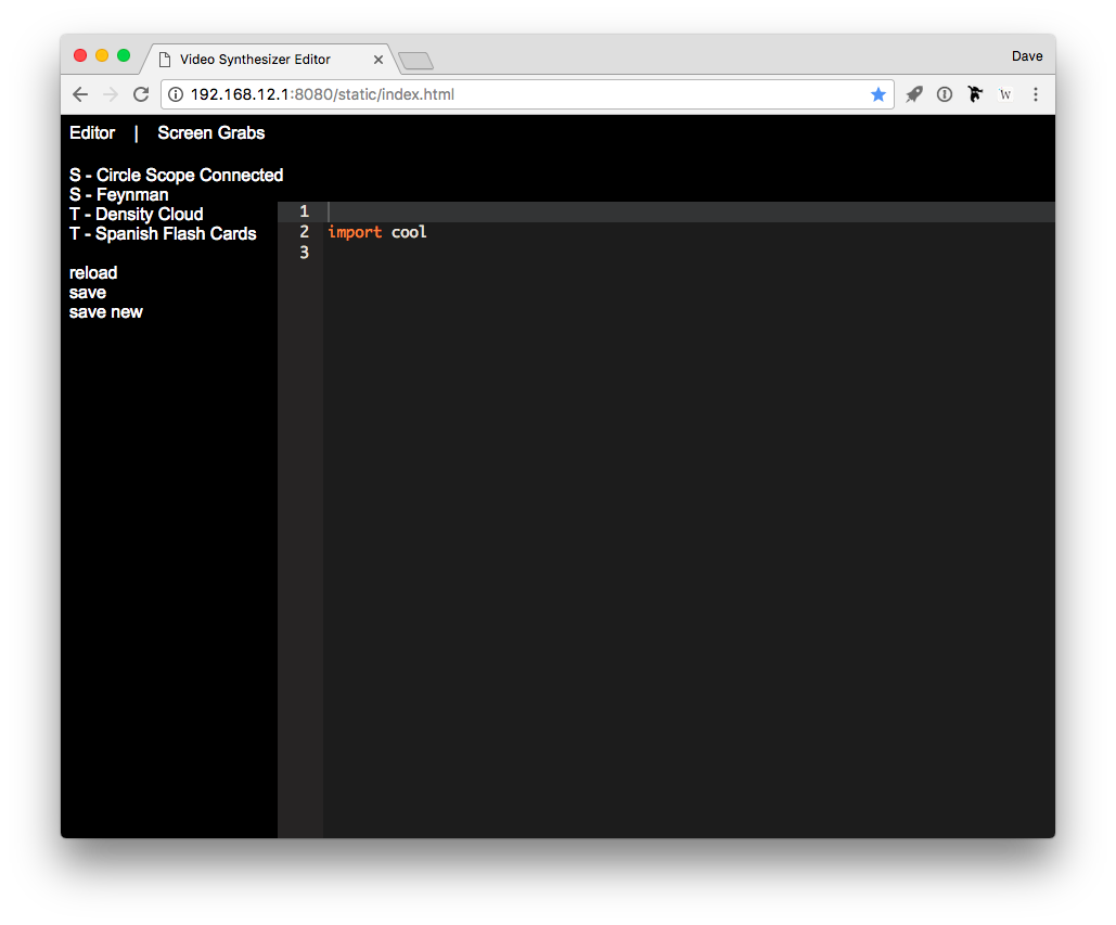
This is the landing page of ETC’s web console. The simple navigation bar in the very top line offers us two pages: Editor and Screen Grabs. The page we are on is the default Editor page, showing a list of the loaded modes on the left, a few function options beneath that list, and a friendly code editor on the right of the screen. By clicking on one of the modes, we will load that mode for viewing and/or editing.
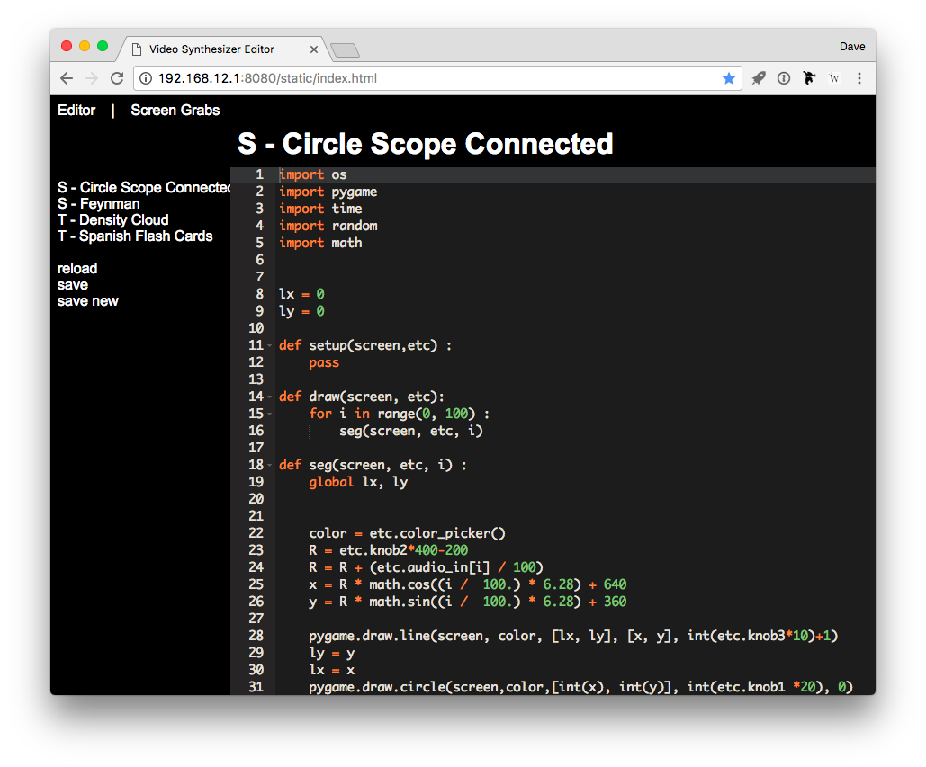
The right side of the window is indeed a code editor, complete with line numbers and syntax highlighting/coloring. You can edit as you would with any basic text editor. After making changes, we will need the functions beneath the mode list. Three functions are available:
reloadrefreshes the list of available modes. You won’t need this too often.savewrites the file you were editing back to the USB drive with any changes you have made.save newcreates a new mode as a copy of the mode currently loaded in the code editor. After clickingsave new, a dialog box appears asking you to name the new mode before its folder is written.
So after altering the mode script in the code editor, click save to commit those changes. This will also cause ETC to reload the current mode, immediately showing you the visual result of your changes via the HDMI output.
By clicking on the Screen Grabs link in the upper navigation bar, the Screen Grabs page is loaded.
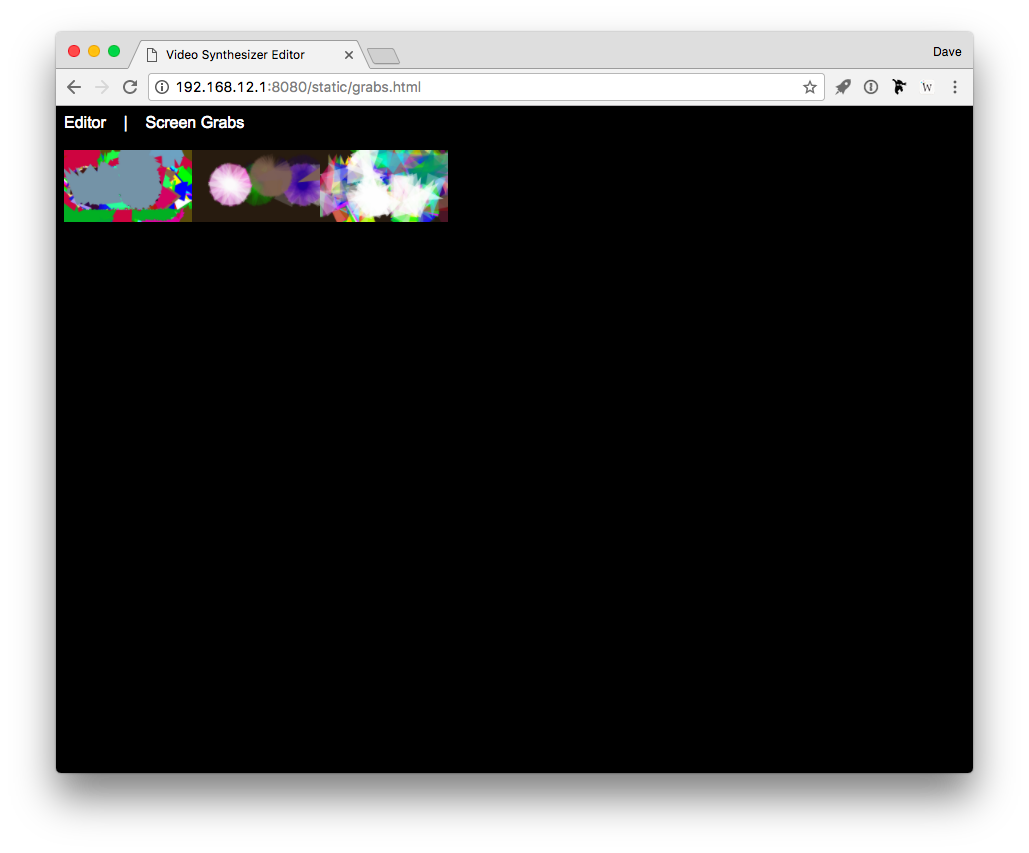
This page displays thumbnails of all stored screenshots. So still using our example file structure from chapter three, here we can see our three screenshots from the USB drive’s Grabs folder. By clicking on any of these thumbnail images, a larger preview is presented.
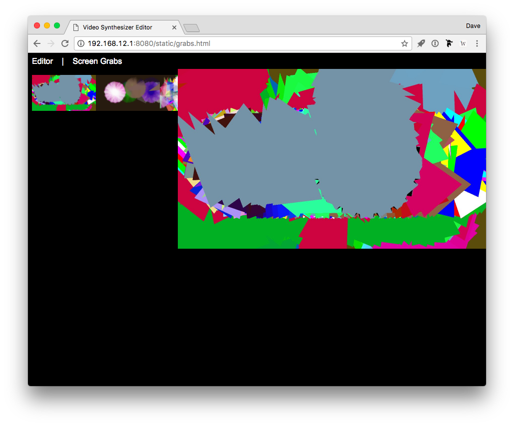
If you want to save a screenshot to your computer, right-click on either the thumbnail or the larger image preview, and then select the context menu option for saving the image. (Both images link to the full resolution version.)
That covers the general overview of ETC’s web console. While some functions must still be done by connecting the USB stick to your computer (see chapter three), the web console allows you both to quickly sample all of the screenshots you have taken and to program on the fly, seeing the results as you go. If you plan on doing your own tweaks and/or programming with ETC, you may want to consider the USB Wi-Fi interface as a small cost yielding a large convenience.
Chapter Five - Appendix
5.1 Burning SD Card Disk Image
In addition to storing modes, the microSD card also stores the ETC's operating system.
Burning a fresh disk image on the microSD card will reset your ETC to the 'factory' state. This is useful to update to the latest ETC OS, to fix a problem with the microSD card, or to burn a new microSD card.
If you are looking to use a new card with the same specifications of the card that shipped with your ETC, those specificaitons are: SanDisk Edge 4GB microSDHC C4 UHS-I.
Follow these steps to burn a new SD card:
Download the microSD card disk image to your computer:
- Current OS release: ETC OS. Requires 4GB or larger microSD card.
Optional: If you want to unzip the disk image please use one of the following programs:
Windows: 7-Zip
Mac: The Unarchiver
Linux: Unzip
Download the flasher program to your computer: https://www.balena.io/etcher/
Power down the ETC.
Locate the thin slit in the rear of the enclosure (between the
MIDI InandHDMIports.)Use a pin or paperclip to press in on the black microSD card to eject it and it will spring out gently.
Insert microSD into your computer (you may need an adapter or card reader)
Use the Etcher program to burn the unzipped OS to the mircoSD card. When Etcher is finished your computer may display a message similar to 'This disk is not readable.' This message is normal and you may click 'Eject' to proceed.
Remove the microSD card from your computer and reinsert it in ETC. Make sure that the SD card is going into the socket on the circuit board, as it is easy to drop it into the device. If you can wiggle it a lot, it probably is not in the socket. Use the same pin/paperclip to press it in until you hear/feel a 'click.'
Restart the ETC.
Notes
This user guide and its content is subject to change without notice. It should not be viewed as a commitment by Critter & Guitari Inc.
Though we aimed for accuracy and clarity herein, Critter & Guitari Inc. is not liable or responsible for errors or inaccuracies occurring in this user guide.
Without prior written permission by Critter & Guitari Inc, no part of this publication may be copied, reproduced, edited or otherwise transmitted or recorded, for any purpose.
“Critter & Guitari” is a registered trademark of Critter & Guitari Inc. “Organelle” is a trademark of Critter & Guitari Inc. “HDMI” is a trademark of HDMI Licensing, LLC. Any other included product and company names are trademarks or registered trademarks of their respective holders. By using them herein we are not implying affiliation with or endorsement by them.
All specifications are subject to change without notice: users should check that they have the most current manual.
For warranty information, please view the document that shipped with your Organelle.
© 2017 Critter & Guitari Inc. All rights reserved.